What
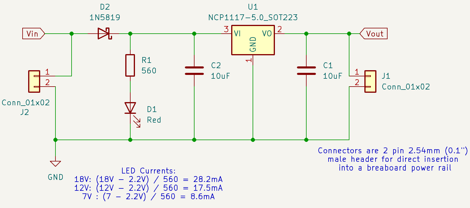
This project involved designing, simulating, and ordering a 5V linear voltage regulator circuit using KiCad. The circuit regulates input voltages between 7V–18V to a steady 5V output, with features such as input protection (with the diode), and operation indicators (LED).
How
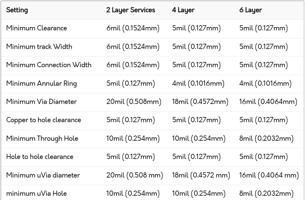
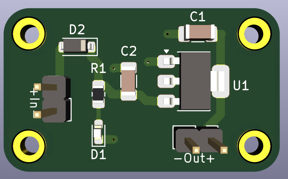
The circuit was designed in KiCad with key components including the NCP1117-5.0 linear regulator, 1N5819 diode for reverse polarity protection, and filter capacitors for stability. The PCB layout emphasized minimal trace lengths, ground planes, and adherence to DRC for manufacturability.
Reflection
This project reinforced skills in PCB design, adhering to DRC, and debugging circuity. Challenges included thermal management and adhering to DRC standards. Future improvements could involve using a switching regulator for improved efficiency and adding test points for easier debugging.