What
This project was thought of when a friend's fish tank heater would over heat the tank for their species of fish leading to them unplugging the heater everyday after heating for a few hours as fish don't like big temperature changes. I thought I could come up with a handmade solution for less than the cost of a new heater. For this project I used an ESP32-WROOM-32D, a 4.7k resistor, 2 DS18B20 temperature sensors and a Sonoff S31 smart plug.
How
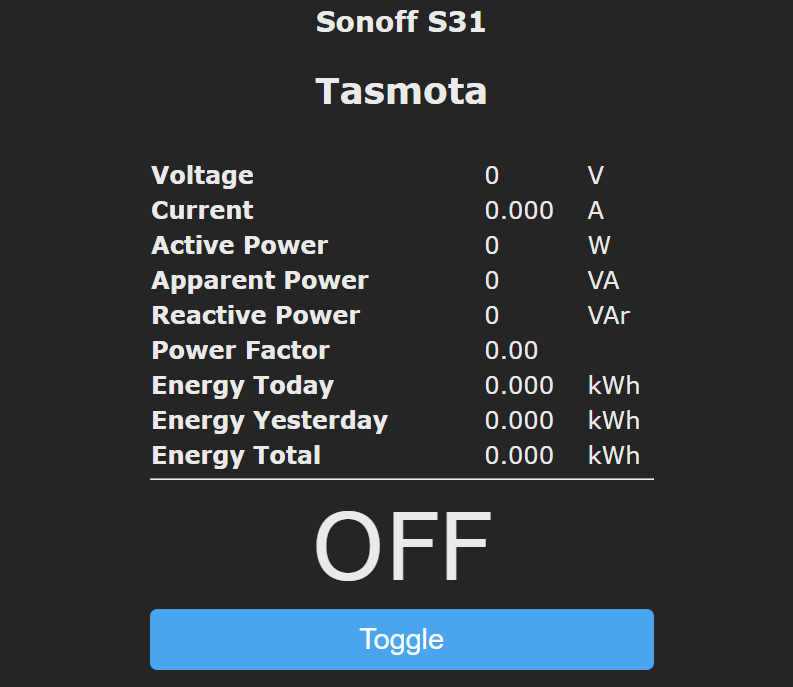
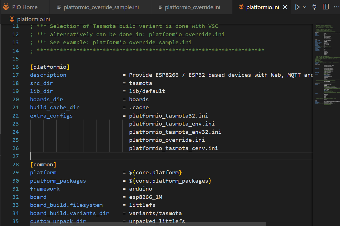
For this project I first flashed the Sonoff S31 smart plug by disassembling the housing and soldering jumper wires onto the internal esp8266 VCC, GND and SDA/SCL pads. Then I customized the Tasmota binary with the help of platformIO and flashed the onboard microcontroller with the custom Tasmota binary. Then I connected the smart plug to the wifi network and set its ip address as static. Next, I customized the Tasmota software with platformIO for the ESP32 microcontroller and flashed that binary. Following a similar process, I connected the ESP32 to the internet and connected the temperature sensors with a 4.7k pullup resistor. Next I configured the ESP32 to read temperature data and made a rule to average both temperature readings and send the smart plug a HTTP signal to toggle ON or OFF based on the current temperature. This would look something like http://192.168.1.20/cm?cmnd=Power%20ON if you wanted to send and ON command to the plug if its IP address was 192.168.1.20. To tidy up the project I soldered all connections and put the ESP32 and connected wires in a box with ventilation to stay cool.
Reflection
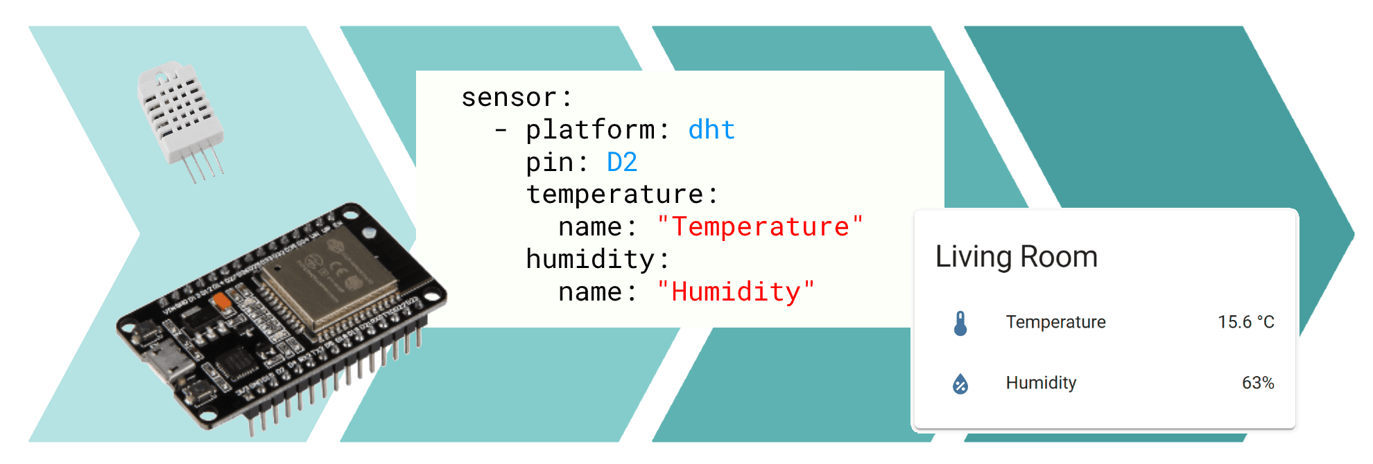
After dropping the waterproof temperature sensors into the tank, plugging the ESP32 into a 5V brick and plugging the heater into the smart plug which was plugged into the wall, everything has worked great. This solution has proven to work well for low device setups and is resilient against power and network outages as it will continually reconnect to the wifi when it comes back up. As a failsafe, the plug will be on if wifi is down and can be manually toggled with a button on the unit. For future projects I would look into using a Raspberry Pi or similar to act as a MQTT broker which can facilitate communication between many nodes and controllers. Popular software to run as an MQTT broker for the ESP family is ESPHome which allows users to view all their sensors on one page and toggle devices such as smart plugs from a custom app rather than IP access.